Viz Artist User Guide
Version 3.13 | Published March 28, 2019 ©
Lens File Editor
The Lens File Editor is used to create and change lens files used by the Tracking Hub for virtual sets. Use the Lens File Editor to calibrate lenses by adjusting the field of view, lens distortion and nodal points for the cameras in use for a virtual studio set.
This section contains information on the following topics:
Lens File Editor Workspace

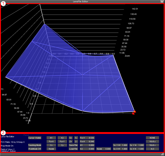
The Lens File Editor workspace consists of two areas; the visualization area (1) and control area (2). The size of the Lens File Editor window can be adjusted by dragging the arrow symbol in the lower right corner of the window frame.

The control area is organized in several sections, for ease of use. Information on the current modes and selected properties is displayed in the far left side of the control area (A) at all times. To the right of this section, the different modes (B) can be set:
-
Cursor Visible/off (B): Displays a cross-hair with guiding lines in the visualization area when in Cursor mode and Cursor is set to Visible.
-
Cursor mode/Tracking mode (B): Uses guiding cross-hairs if set to Cursor mode, or use tracking position data received from the tracking system when in Tracking mode.
-
ProbMode On/Off (B): Updates the FoV Y value automatically according to changes to the FoV X value if ProbMode is set to On when in free aspect ratio mode.
The next section (C) is used to select which parameter is displayed in the visualization area (1):
-
K1/K2 (C): Displays the current adjustments to the distortion values K1 and K2, respectively. The K1 and K2 values are used to correct for lens distortion.
-
FoVX/FoVY (C): Shows the Field of View controls, used to define the field of view for the selected camera, for the X and Y planes, respectively.
-
Cx/Cy (C): Shows the center shifts when zooming out due to imperfect mount of lens on camera body. Corrections to the center shift are derived from the values given here for the X and Y planes, respectively.
-
Nodal (C): Displays the configured nodal point for the current lens setup. The Nodal point changes when changing zoom and focus, and can change with as much as up to 20 centimeters for most broadcast lenses.
The middle section (D) is used to change the resolution and zoom level in the visualization area, as well as saving and loading lens files:
-
S+/S- (D): Increases or decreases the value resolution of the visualization area (1).
-
Z+/Z- (D): Zooms in to or out of the visualization area (1).
-
Save/Load File (D): Saves the current setup to a new lens file or load a previous setup.
The next three sections (E, F and G) display the numeric representations of the current field of view, lens distortion, nodal point and linear scaling. The values are automatically updating when adjustments are made to the splines within the visualization area. Values can also be manipulated directly by clicking and holding the value to be adjusted, then dragging the mouse left or right to adjust the value up or down, respectively:
-
FovY/FovX: Displays the current Field of View values for the X and Y planes.
-
K1/K2: Displays the current lens distortion values.
-
Nodal: Displays the current nodal point value.
-
Sc Y W: Displays the linear scaling Wide value for the Y axis, for field of view adjustments.
-
Sc X W: Displays the linear scaling Wide value for the X axis, for field of view adjustments.
-
Sc Y N: Displays the linear scaling Near value for the Y axis, for field of view adjustments.
-
Sc X N: Displays the linear scaling Near value for the X axis, for field of view adjustments.
The far right section (H) is used to select the aspect ratio for the current lens:
-
NONE: Free aspect ratio.
-
16x9 y: Sets aspect ratio to 16:9.
-
16x 9 x: Sets aspect ratio to 16:9.
-
4x3: Sets the aspect ratio to 4:3.
Lens File Editor Contextual Menu
Click and hold the right mouse button anywhere in the visualization area of the Lens File Editor to bring up the contextual menu. Select an option by moving the mouse cursor and release the button.

-
Select Camera: Up to 16 cameras can be configured in the same lens file. Select which camera to modify settings for.
-
Parameter: Select which parameter to display in the visualization area:
-
K1, K2: Displays splines for the lens distortion parameters.
-
FovX, FovY: Displays splines for the field of view parameters.
-
CenterX, CenterY: Displays splines for the center shift parameters.
-
Nodal: Displays splines for the nodal point parameter.
-
-
Display Mode: Select the display mode for the visualization area:
-
Triangulation: Shows the default view.
-
Grid: Displays a grid overlay.
-
Cut Focus: Displays lines to check the curve quality.
-
Cut Zoom: Displays lines to check the curve quality.
Note: The visualization area is not automatically updated if making changes to parameters while Display Mode is in Cut Focus or Cut Zoom mode
-
-
Merge From: Copies settings from another previously configured camera (1-16).
-
Create: Creates a new raw lens with 3x3, 5x5, 7x7 or 9x9 reference points. It is recommended to start with a 3x3 configuration, then use the Insert option to add more reference points after successful 3x3 calibration.
-
Insert: Inserts more reference points. Available insertions are:
-
5x5
-
7x7
-
9x9
-
To Create a New Lens
-
In Viz Artist, click the On Air button.
-
Click the Show Lens File Calibration Editor button.
-
Right click in the visualization area and select Create, then 3x3.
-
Select a parameter to bring up the spline editor for adjustments.